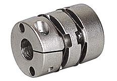
Features
|
・Anti-misalignment, multi-purpose. ・Stainless steel - Inferior flexibility, but high transmission torque and torsional rigidity, so it is optimal for highly responsive servo systems. |
 |
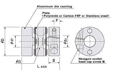
Configuration and materials
 |
|
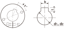
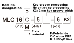
Dimensions of key groove shape |
|
||||||||||||||||||||||||||||||||||||||||||||||
Dimensions
| Item No. | D |
Standard hole diameters φd1,φd2 H8 (left/right can be freely combined.) | L | B | F |
G diameter |
H diameter |
M | Fastening torque (N・m) | ||||||||||||
|---|---|---|---|---|---|---|---|---|---|---|---|---|---|---|---|---|---|---|---|---|---|
| MLC | 13 | 3 | 4 | 5 |
19 |
5.5 | 2.5 | 5.3 | 6 | 2 | 0.42 | ||||||||||
| 16 | 4 | 5 | 6 |
23.2 |
7 | 3 | 6.8 | 7.6 | 2.5 | 0.9 | |||||||||||
| 20 | 4 | 5 | 6 | 6.35 | 8 |
26 |
7.5 | 3.7 | 8.1 | 9 | 2.5 | 1 | |||||||||
| 25 | 5 | 6 | 6.35 | 8 | 10 |
30.2 |
9 | 4 | 10.4 | 12 | 3 | 1.7 | |||||||||
| 32 | 6 | 8 | 10 | 12 | 14 |
41 |
12.4 | 6 | 15 | 15.2 | 4 | 2.5 | |||||||||
| 40 | 8 | 10 | 12 | 14 | 16 | 18 |
47 |
15.5 | 7.8 | 19.5 | 20.4 | 5 | 7 | ||||||||
| 50 | 14 | 16 | 18 | 20 | 22 | 24 |
53 |
18 | 9 | 25 | 26 | 6 | 12 | ||||||||
・Recommended tolerance of applied axial diameter is h6 and h7.
・Two bolts with hexagonal sockets included.
Specifications
| Item No. | Allowable torque (N⋅m) | Maximum rotating speed (rpm) | Torsional rigidity (N⋅m/rad) | Allowable parallel misalignment (mm) | Allowable angular misalignment (°) | Allowable end play (mm) | Moment of inertia (kg⋅m2) | Mass (g) | |
|---|---|---|---|---|---|---|---|---|---|
| MLC13 | P | 0.25 | 12,000 | 30 | 0.4 | 5 | ±0.2 | 8.0x10⁻⁸ | 5 |
| C | 0.35 | 12,000 | 90 | 0.2 | 2.5 | ±0.2 | |||
| MLC16 | P | 0.4 | 9,000 | 60 | 0.6 | 5 | ±0.3 | 2.4x10⁻⁷ | 9 |
| C | 0.6 | 9,000 | 140 | 0.2 | 2.5 | ±0.3 | |||
| M | 0.9 | 7,000 | 400 | 0.15 | 2 | ±0.2 | 2.7x10⁻⁷ | 10 | |
| MLC20 | P | 0.6 | 7,600 | 110 | 0.6 | 5 | ±0.4 | 7.2x10⁻⁷ | 14 |
| C | 1.0 | 7,600 | 230 | 0.2 | 2.5 | ±0.3 | |||
| M | 1.3 | 6,500 | 700 | 0.15 | 2 | ±0.2 | 8.0x10⁻⁷ | 16 | |
| MLC25 | P | 1.4 | 6,000 | 150 | 0.6 | 5 | ±0.6 | 2.2x10⁻⁶ | 27 |
| C | 2.2 | 6,000 | 450 | 0.2 | 2.5 | ±0.4 | |||
| M | 2.8 | 5,000 | 1,100 | 0.15 | 2 | ±0.3 | 2.5x10⁻⁶ | 30 | |
| MLC32 | P | 2.6 | 4,800 | 380 | 0.6 | 5 | ±0.6 | 6.0x10⁻⁶ | 60 |
| C | 3.8 | 4,800 | 750 | 0.2 | 2.5 | ±0.4 | |||
| M | 5.0 | 4,000 | 1,500 | 0.15 | 2 | ±0.4 | 6.6x10⁻⁶ | 62 | |
| MLC40 | P | 4.4 | 4,000 | 650 | 0.6 | 5 | ±0.8 | 1.7x10⁻⁵ | 104 |
| C | 6.8 | 4,000 | 900 | 0.3 | 2.5 | ±0.5 | |||
| M | 9.0 | 3,800 | 4,000 | 0.2 | 2 | ±0.5 | 1.9x10⁻⁵ | 110 | |
| MLC50 | P | 7.0 | 3,500 | 850 | 0.6 | 5 | ±1 | 4.6x10⁻⁵ | 210 |
| C | 11.0 | 3,500 | 1,500 | 0.3 | 2.5 | ±0.6 | |||
| M | 16.0 | 3,500 | 8,000 | 0.2 | 2 | ±0.6 | 5.0x10⁻⁵ | 220 | |
・Heat resistance(ambient temperature): polyimide:-40℃ to 200℃, carbon FRP:-25℃ to85℃ *1/2 the allowable torque should be used at maximum temperature.
・Maximum torque is basically twice as large as allowable torque. When selecting size, please note that applied torque must be equal to or less than the given value for allowable torque, and its instantaneous maximum load torque must be equal to or less than the given value for maximum torque.

 ・Key groove shape complies with new JIS standards.