Features
|
・Two different sizes for outer diameter; ø24、ø28 and ø33. |
 |
Applications
・For prevention of displacement in servo positioning.
・For prevention of natural fall of a nut of vertical ball screw.
・Maintaining the position of the robot (when not energized).
Operating mechanism
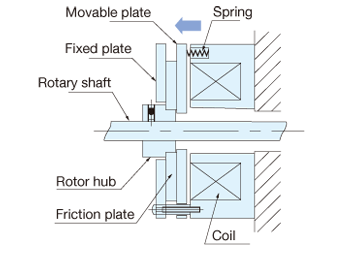
Brake actuated
(when the coil is de-energized.)
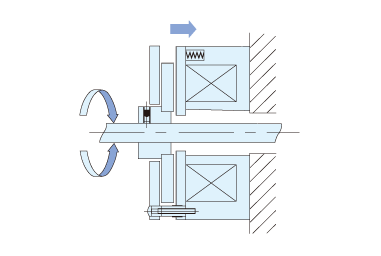
Brake in release position
(when the coil is energized)
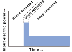
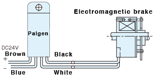
Mechanism of Parugen; a dedicated power supply unit
|
After a coil as electromagnet pulls in a movable plate and releases the brake, the necessary electric power becomes less during the hold status compared to the time to start releasing. Parugen is a dedicated driving power supply that transmits huge electric power temporarily upon brake release, and reduces the power transmission during a hold state. |
 |
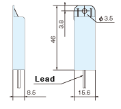
Outside dimension of Parugen
Connection diagram of Parugen
Dimensions

| A | B | D | F | G | H | L | S | α | d | |
|---|---|---|---|---|---|---|---|---|---|---|
| MB3 | 16.7 | 6.0 | 33+0-0.1 | 9 | M3 | M3 Thread depth 6 |
27 | 29 | 110° | 6/8 |
| MB2 | 12.7 | 4.8 | 28+0-0.1 | 5.8 | M2 | M2.6 Thread depth 5 |
20.3 | 24.8 | 60° | 3/4/5 |
| MB2S | 8.8 | 3.5 | 28+0-0.1 | 6.5 | M2.5 | M2 Thread depth 5 |
15.7 | 25 | 60° | 4/5/6 |
| MB24P24 | 8 | 3.2 | 24+0-0.1 | 5.5 | M2 | M1.6 Thread depth 5 |
14.2 | 22 | 60° | 3/4/5 |
| MB20P24 | 10.1 | 3.2 | 20+0-0.1 | 3.4 | M1.6 | M1.4 Thread depth 3.5 |
16.7 | 17.9 | 60° | 2/2.5/3 |
Specifications
| Type | Non-Parugen spec. |
Parugen spec. | Non-Parugen spec. |
Parugen spec. | Non-Parugen spec. |
Parugen spec. |
Parugen spec. |
Parugen spec. |
|---|---|---|---|---|---|---|---|---|
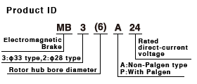
| MB3( )A24 | MB3( )P24 | MB2( )A24 | MB2( )P24 | MB2S( )A24 | MB2S( )P24 | MB24( )P24 | MB20( )P24 | |
| Rated voltage | DC24V | |||||||
| Max. instantaneous power | - | 7.2W | - | 8.1W | - | 7.6W | 8.5W | 6.7W |
| Power consumption | 2.4W | 1W or lower | 1.6W | 1W or lower | 1.6W | 1W or lower | ||
| Static friction torque | 20N⋅cm | 36N⋅cm | 16N⋅cm | 25N⋅cm | 12N⋅cm | 18N⋅cm | 10N⋅cm | 7N⋅cm |
| Armature pull in time | 40msec or lower. | |||||||
| Armature release time | 10msec or lower. | |||||||
| Pull in voltage | 20V or lower | |||||||
| Release voltage | 3V or more | 10V or more | 3V or more | 10V or more | 3V or more | 10V or more | ||
| Moment of inertia | 3.2g・cm2 | 1.7g・cm2 | 1.2g・cm2 | 0.9g・cm2 | 0.3g・cm2 | |||
| Insulation resistance | 10MΩ or more with DC500V megger | |||||||
| Withstand voltage | 1 min at AC1000V | |||||||
| Insulation classification | F type | |||||||
| Weight | 100g | 112g | 57g | 66g | 39g | 49g | 42g | 33g |
| Rotor hub bore diameter | ø6,ø8(H7) | ø3,ø4,ø5(H7) | ø4,ø5,ø6(H7) | ø3,ø4,ø5(H7) | ø2,ø2.5,ø3(H7) | |||
Precautions
・Please take care to prevent water or oil from adhering to the friction surface.
・Please apply preventive measures against loosening to unit set screw.
・When installing the unit, make sure to place the rotor hub kept from being in contact with the movable plate.
