Selection of Couplings
|
Couplings that connect two shafts have a vast range of applications. As manufacturers, we produce couplings to suit particular kinds of applications, by carefully considering the way in which the coupling will be used. |
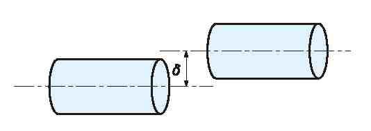 Parallel-Offset Misalignment Parallel-Offset Misalignment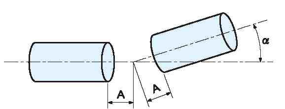 Angular Misalignment Angular Misalignment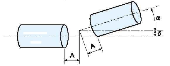 Non-Symmetrical Misalignment Non-Symmetrical Misalignment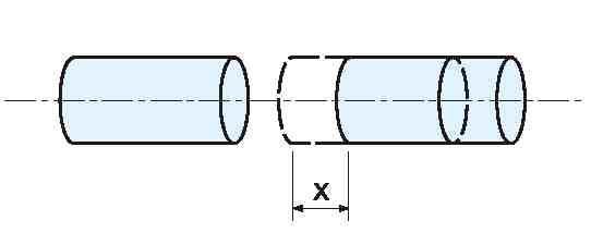 End Play End Play Eccentricity Eccentricity |
Rotational Speed
In the design of normal couplings (excluding couplings for low-speed applications) the allowable torque is determined by assuming a rotational speed of about 3000 rpm. Accordingly, if a coupling is operated at a maximum speed of 6000 rpm (double the design value), for safety purposes the allowable torque should be limited to less than 50% of the rated value (at 3000rpm). (This value is not precise, since factors such as the increase of vibration and resisting force with speed depend on the specific coupling and its design. Note that in the case of continuous operation at a constant speed it is acceptable to use a factor of 100% to determine the allowable torque.)
Parameters in Performance Tables
The parameters listed in coupling performance tables (allowable torque, allowable parallel and angular misalignments, maximum speed, etc.) are determined based on investigations of each performance factor. Therefore, in the case when misalignments are combined, it is essential to divide each of these allowable values by the number of types of misalignment. (Customers sometimes complain that this seems like a strange concept. To help explain this, let us assume that the allowable torque is determined under a situation in which all misalignments are at their maximum allowable levels. In such a case, the total allowable torque is very low, resulting in low practicability for the application. Couplings are elemental components that transmit energy, so the types and magnitude of internal stresses significantly affect their lifetime.)
Relationship between misalignment and life of couplings
As an example, consider the plastic mold couplings in our UJ and GJ series. We determined the allowable parallel misalignment to be 1/2.5 to 1/3 of the value of the displacement where the force and parallel misalignment vary linearly when an external force is applied (elastic limit). Please refer here for the results of operational life tests conducted over 3 years for each misalignment. We conducted our tests for up to one billion rotations, but we are unable to say how many years of use by customers this figure is equivalent to. Note that for the M Series, we conducted tests on the relationship between misalignment and lifetime for each plate material (i.e., polyimide, carbon FRP, and stainless steel). Click here for details.