Features
|
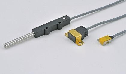
Proximity switches for detecting ferromagnetic materials such as ferrous metals. Not react to such materials as aluminim or nonmagnetic stainless steel. |
 |
Mechanism
|
Sensors are deactivated because magnet is being pushed by springs and the detection circuit is within the N-pole magnetic field. |
 |
|
When a ferromagnetic object such as ferrous metals approaches the sensing face, magnet is pulled toward the object. Then, the sensing sirsuit detects S-pole and the switch is activated. |
 |
Common specifications
|
WARNING
・Ferrous proximity switches are not suitable for detecting tiny loose terromagnetic
materials such as iron powders because they are easily stuck to magnets.
・When mounting a ferrous proximity switch, please check that there ia no
ferromagnetic material at the back and lateral sides.
| Model | Diagrams(mm) | Specifications | ||||||||||||||||||||||||||||||||
|---|---|---|---|---|---|---|---|---|---|---|---|---|---|---|---|---|---|---|---|---|---|---|---|---|---|---|---|---|---|---|---|---|---|---|
|
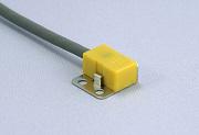
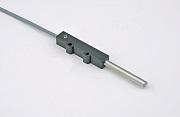
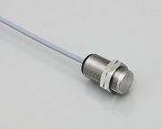
AR001 AR001(B) |
|
・By using cable options, conversion of output specifications, current amplification, and cable extension are possible. |
||||||||||||||||||||||||||||||||
|
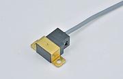
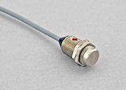
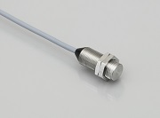
AR002 AR002(B) |
|
・By using cable options, conversion of output specifications, current amplification, and cable extension are possible. |
||||||||||||||||||||||||||||||||
|
AR101 AR101(B)
|
|
|
||||||||||||||||||||||||||||||||
|
AR012 AR012(B) |
|
・By using cable options, conversion of output specifications, current amplification, and cable extension are possible.
■Maximum Sensing distance
< Notes >
|
||||||||||||||||||||||||||||||||
|
AR013 AR013(B)
|
|
・By using cable options, conversion of output specifications, current amplification, and cable extension are possible. |
||||||||||||||||||||||||||||||||
|
AR014 AR014(B)
|
|
・By using cable options, conversion of output specifications, current amplification, and cable extension are possible. |
||||||||||||||||||||||||||||||||