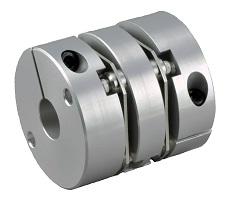
Features
|
・Strong structure achieved by press-fitting assembly of plate and flanged collar, and by insertion into hub. |
 |
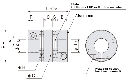
Configuration and materials
 |
|
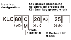 ・Key groove shape complies with new JIS standards.
Dimensions of key groove shape |
|
|||||||||||||||||||||||||||||
Dimensions
| Item No. | D |
Standard hole diameters φd1,φd2 H8 (left/right can be freely combined.) | L | F | B | C |
G diameter |
H diameter | A | M | Fastening torque (N・m) | |||||||||
|---|---|---|---|---|---|---|---|---|---|---|---|---|---|---|---|---|---|---|---|---|
| KLC | 60 | 18 | 20 | 22 | 25 | 28 |
64 |
8 | 19 | 14 | 28.5 | 30.4 | 20.5 | 6 | 13 | |||||
| 70 | 20 | 22 | 25 | 28 | 30 | 32 |
71.4 |
9 | 21 | 15 | 33 | 33.6 | 25 | 6 | 13 | |||||
| 80 | 20 | 22 | 25 | 28 | 30 | 32 | 35 |
94 |
10 | 29 | 20 | 38 | 36.4 | 28 | 8 | 30 | ||||
・Recommended tolerance of applied axial diameter is h6 and h7.
・Two bolts with hexagonal sockets included.
Specifications
| Item No. | Allowable torque (N⋅m) | Maximum rotating speed (rpm) | Torsional rigidity (N⋅m/rad) | Allowable parallel misalignment (mm) | Allowable angular misalignment (°) | Allowable end play (mm) |
Radial rigidity (Shearing Rigidity) (N/mm) |
Axial rigidity (N/mm) | Moment of inertia (kg⋅m2) | Mass (g) | |
|---|---|---|---|---|---|---|---|---|---|---|---|
| KLC60 | C | 55 | 10,000 | 15,000 | 0.8 | 4 | 1.0 | 290 | 80 | 1.6x10⁻⁴ | 360 |
| M | 60 | 10,000 | 17,000 | 0.25 | 1.5 | 0.3 | 250 | 50 | 1.9x10⁻⁴ | 380 | |
| KLC70 | C | 60 | 10,000 | 20,000 | 1.0 | 4 | 1.0 | 250 | 65 | 4.0x10⁻⁴ | 600 |
| M | 80 | 10,000 | 30,000 | 0.3 | 1.5 | 0.3 | 240 | 45 | 4.4x10⁻⁴ | 630 | |
| KLC80 | C | 80 | 10,000 | 40,000 | 1.2 | 4 | 1.2 | 250 | 55 | 9.0x10⁻⁴ | 1,000 |
| M | 100 | 10,000 | 50,000 | 0.45 | 1.5 | 0.4 | 240 | 40 | 9.3x10⁻⁴ | 1,040 | |
・Heat resistance(ambient temperature):stainless steel:-40℃ to 200℃, carbon FRP:-25℃ to 85℃
*1/2 the allowable torque should be used at maximum temperature.