Features
|
・More allowable misalignment at single use due to longer slits than UJ series. ・Suitable for rotary transmissions requiring electrical insulation. |
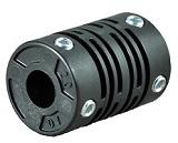 |
Configuration and materials
|
|
Cautions when using plastic couplings |
Dimensions
| Item No. | d1 |
Standard hole diameters ød1,ød2 H8 (left/right can be freely conbined) | D | L | F | B | Set screw | ||||||||||||||||||||||||||
|---|---|---|---|---|---|---|---|---|---|---|---|---|---|---|---|---|---|---|---|---|---|---|---|---|---|---|---|---|---|---|---|---|---|
| M | Fastening torque (N⋅m) | ||||||||||||||||||||||||||||||||
| GJ
|
1.5 | 1.5 | 9 | 11.4 | 1.6 | 3.2 | 2 | 0.08 | |||||||||||||||||||||||||
| 1.5 | 2.5 | 10 | 11.8 | 1.7 | 3.2 | 2 | 0.08 | ||||||||||||||||||||||||||
| 2 | 2 | 9 | 13.2 | 1.6 | 3.2 | 2 | 0.08 | ||||||||||||||||||||||||||
| 3 | 3 | 12 | 20 | 2.6 | 5.1 | 3 | 0.15 | ||||||||||||||||||||||||||
| 4 | 4 | 13 | 21 | 2.7 | 5.2 | 3 | 0.2 | ||||||||||||||||||||||||||
| 5 | 5 | 14 | 21 | 2.7 | 5.2 | 3 | 0.2 | ||||||||||||||||||||||||||
| 6 | 6 | 15 | 22 | 2.8 | 5.4 | 3 | 0.25 | ||||||||||||||||||||||||||
| 8 | 8 | 19 | 24 | 3.5 | 7 | 4 | 0.4 | ||||||||||||||||||||||||||
| 10 | 10 | 22 | 26 | 3.6 | 7.1 | 4 | 0.5 | ||||||||||||||||||||||||||
| G2J | 4 | 2.5 | 3 | 3.2 | 4 | 13.5 | 21 | 2.7 | 5.3 | 3 | 0.25 | ||||||||||||||||||||||
| 5 | 3 | 3.2 | 4 | 5 | 15 | 20.5 | 2.7 | 5.3 | 3 | 0.25 | |||||||||||||||||||||||
| 6 | 3 | 3.2 | 4 | 5 | 6 | 16 | 21 | 2.7 | 5.5 | 3 | 0.3 | ||||||||||||||||||||||
| 8 | 4 | 5 | 6 | 8 | 20 | 24 | 4 | 7.4 | 4 | 0.45 | |||||||||||||||||||||||
| GJK |
9.53 | 9.53 | 25 | 32.2 | 3.8 | 7.4 | 4 | 0.65 | |||||||||||||||||||||||||
| 10 | 10 | 25 | 32.2 | 3.8 | 7.4 | 4 | 0.65 | ||||||||||||||||||||||||||
| 12 |
|
12 | 28 | 34.4 | 3.9 | 7.5 | 4 | 0.8 | |||||||||||||||||||||||||
Specifications
|
Item No. (d1-d2) |
Allowable torque (N⋅m) |
Maximum Rotating speed (rpm) | Torsional rigidity (N⋅m/rad) |
Allowable parallel misalignment (mm) |
Allowable angular misalignment (°) |
Allowable end play (mm) | Moment of inertia (kg⋅m2) | Mass | Materials | |
|---|---|---|---|---|---|---|---|---|---|---|
| (g) | ||||||||||
| GJ | 1.5-1.5 | 0.16 | 4,000 | 4 | 0.2 | 3 | ±0.3 | 1.0x10⁻⁸ | 0.9 | GFR PBT |
| 1.5-2.5 | 0.22 | 4,000 | 5 | 0.2 | 3 | ±0.3 | 1.4x10⁻⁸ | 1.1 | ||
| 2-2 | 0.18 | 4,000 | 3.5 | 0.3 | 4 | ±0.3 | 1.0x10⁻⁸ | 1.0 | ||
| 3-3 | 0.35 | 4,000 | 8 | 0.4 | 5 | ±0.3 | 4.5x10⁻⁸ | 2.5 | ||
| 4-4 | 0.5 | 4,000 | 8 | 0.4 | 5 | ±0.4 | 7.0x10⁻⁸ | 3.1 | ||
| 5-5 | 0.55 | 5,000 | 10 | 0.5 | 5 | ±0.4 | 9.0x10⁻⁸ | 3.3 | ||
| 6-6 | 0.8 | 6,000 | 16 | 0.5 | 5 | ±0.4 | 1.2x10⁻⁷ | 3.9 | ||
| 8-8 | 1.2 | 8,000 | 40 | 0.5 | 5 | ±0.4 | 3.9x10⁻⁷ | 7.3 | ||
| 10-10 | 1.7 | 10,000 | 60 | 0.5 | 5 | ±0.4 | 7.0x10⁻⁷ | 10.0 | ||
| G2J | 4-d | 0.5 | 5,000 | 6 | 0.4 | 5 | ±0.4 | 8.0x10⁻⁸ | 3.4 | |
| 5-d | 0.6 | 6,000 | 12 | 0.4 | 5 | ±0.4 | 1.0x10⁻⁷ | 4.0 | ||
| 6-d | 0.8 | 6,000 | 18 | 0.5 | 5 | ±0.4 | 1.3x10⁻⁷ | 4.5 | ||
| 8-d | 1.4 | 8,000 | 50 | 0.5 | 5 | ±0.4 | 4.0x10⁻⁷ | 7.5 | ||
| GJK | 9.53-9.53 | 2.2 | 10,000 | 100 | 0.4 | 4 | ±0.4 | 1.3x10⁻⁶ | 15 | |
| 10-10 | ||||||||||
| 12-12 | 3 | 12,000 | 80 | 0.4 | 4 | ±0.4 | 2.1x10⁻⁶ | 19 | ||
・Heat resistance (ambient temperature):GFR PBT,-30℃ to 85℃
・Note:When the ambient temperature to be used is the maximum, the permissible torque is 1/2 of the value in the table.