Features
|
・Disk material made up of polyimide, for its high flexibility, and carbon FRP, for its high torque capabilities. ・No key groove or other shaft processing necessary for taper lock type couplings. ・Set screw type and taper lock type couplings can be combined freely. |
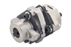 |
Configuration and materials
  |
|
 ・Key groove shape complies with new JIS standards.
Dimensions of key groove shape |
|
||||||||||||||||||||||||||||||
How to tighten taper locks
1.After completing positioning, use a torque wrench to tighten the locking bolts on oppsing diagonal sides, first lightly (to roughly 1/4 of the specified tightening torque).
2.Increase the tightening torque, tightening each bolt again (to roughly 1/2 the specified tightening torque).
3.Tightening each bolt again the specified tightening torque.
4.Finally, tightening the locking bolts in order in circumferential direction.
Dimensions
|
Standard hole diameters ød1,ød2 H8 (left/right can be freely combined) |
Hub configuration |
L | M |
Fastening torque (N・m) |
||
|
Set screw type |
(P1 hub) 14, 15, 16, 18 |
(L1 hub) 20, 22, 24, 25, 28, 30 |
P1+P1 | 78 | 5 | 1.7 |
| P1+L1 | ||||||
| L1+L1 | ||||||
|
taper lock type |
(P2 hub) 14, 15, 16 |
(L2 hub) 18, 20, 25 |
P2+P2 | 85 | 4 | 2.0 |
| P2+L2 | 82 | |||||
| L2+L2 | 79 | |||||
| Mixed type |
(P1 hub) 14, 15, 16, 18 (P2 hub) 14, 15, 16 |
(L1 hub) 20, 22, 24, 25, 28, 30 (L2 hub) 18, 20, 25 |
P1+P2 | 81.5 | - | - |
| P2+L1 | ||||||
| P1+L2 | 78.5 | - | - | |||
| L1+L2 | ||||||
・Precautions regarding tightening
After inserting the shaft in the coupling, tighten the locking bolts. If you tighten the bolt before inserting, the coupling deforms.
Use a torque wrench to tighten locking bolts.
Only use the locking bolts supplied with the coupling.
Only perform work when the device is completely stopped.
・Removal
Only perform work when the device is completely stopped.
Loosen the locking bolts in order in circumferential direction.
Insert bolts into the removal bolt holes and tighten equally.
When installing again,repeat the tightening procedure to retighten bolts.
Specifications
|
Item No. |
Disk material |
Allowable torque (N⋅m) |
Maximum rotating speed (rpm) |
Torsional rigidity (N・m/rad) |
Allowable parallel (mm) |
Allowable angular (°) | Moment of inertia (kg⋅cm2) | Mass |
|---|---|---|---|---|---|---|---|---|
| (g) | ||||||||
| C2LPJ | Polyimide 1t | 20 | 4,000 | 2,000 | 0.8 | 5 | 500-900 | 200-350 |
| C2LCG |
Carbon 0.6t |
30 | 6,000 | 3,500 | 0.5 | 4 | ||
| C2LCH |
Carbon 0.8t |
40 | 8,000 | 5,000 | 0.4 | 3 |
・Hole processong can be performed separately (for set screw types only).