Features
|
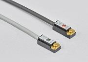
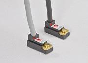
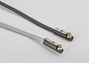
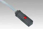
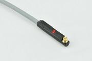
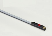
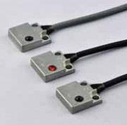
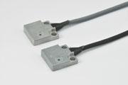
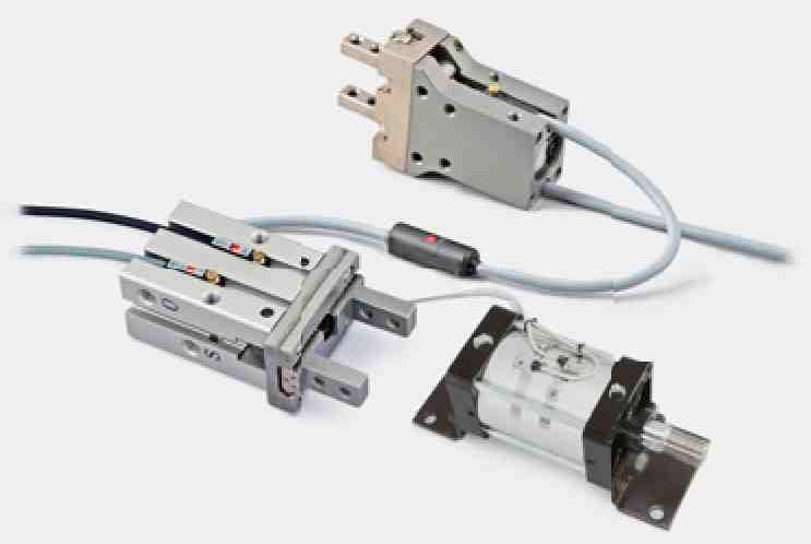
Sensors for Air Cylinders detect the movement of magnetic field which is emitted from a magnet mounted on air cylinder piston. These sensors are capable of stable and high precision operations because of having a operatong point on steep area of the aperating curve. N-pole and S-pole sensors shall be used in combination.
|
 |
In case of the conventional product
| ・Fig-1 Operating Curve of Conventional sensor ・Fig-2 Operating curve of Hall Effect IC based Sensors |
|
Air cylinder sensors are activated / deactivated by sensing the magnetism of a ring magnet installed in a cylinder piston. Since conventional sensor pick up the intensity of the magnetism regardless of the magnetic direction, the operating curve takes a chevron pattern with the magnet center at the peaking point as shown in figure 1. Because the operating points of such sensors are on the gentle slopes of operating curves, a stroke of 5mm or shorter is hard to be detected, which makes a long, stable operation difficult.
With an air cylinder sensors employing Hall Effect IC we offer, the operating curve, as shown in figure 2, takes a very different shape from that of a conventional sensors, because a Hall Effect IC switch picks up only the magnetism vertical against the sensing face. The operating points being on the steep slopes of the operating curves allows a Hall Effect IC switch to detect a small stroke without fail, and to perform stable operation for a long time. In a normal use operation, both N-pole and S-pole sensors will be used in combination. |
Common specifications
|
・3-wire systems
|
・2-wire systems
|
*By using cable options, conversion of output specifications, current amplification, and cable extension are possible.
・The circuit diagram must be observed to ensure a correct connection. A reverse connection and a short-circuiting output are strictly prohibited.
・When connecting an inductive load such as relay, be sure to use a freewheeling diode. (Some models already include a built-in freewheeling diode.)
・When installing a sensor, use the torque value designated for each sensor.
・When handling / using the product, do not apply an excessive tension to the cable connection part.
| Model | Diagrams(mm) | Specifications | ||||||||||||||||||||||||||||||||
|---|---|---|---|---|---|---|---|---|---|---|---|---|---|---|---|---|---|---|---|---|---|---|---|---|---|---|---|---|---|---|---|---|---|---|
|
ACH01
ACH01L |
|
|
||||||||||||||||||||||||||||||||
|
ACH01P
ACH01LP |
|
*If you need the maximum output current(80mA),use a 12V to 24V power supply. ・By using cable options, conversion of output specifications,current current amplification, and cable extension are possible. |
||||||||||||||||||||||||||||||||
|
ACH02
ACH02L
|
|
|
||||||||||||||||||||||||||||||||
|
ACH02P
ACH02LP |
|
*If you need the maximum output current(80mA),use a 12V to 24V power supply. ・By using cable options, conversion of output specifications,current current amplification, and cable extension are possible. |
||||||||||||||||||||||||||||||||
|
AH006 |
■Mounting bracket
|
|
||||||||||||||||||||||||||||||||
|
AH007 |
|
・By using cable options, conversion of output specifications,current amplification, and cable extension are possible. |
||||||||||||||||||||||||||||||||
|
AH008R AH008U |
 |
・By using cable options, conversion of output specifications, current amplification, and cable extension are possible. |
||||||||||||||||||||||||||||||||
|
AH0092 |
 |
・Be sure to connect to the load before use. |
||||||||||||||||||||||||||||||||
|
AH009 |
|
*If you need the maximum output current (80mA), use a 12V to 24V power supply. |
||||||||||||||||||||||||||||||||
|
AH009E |
|
・By using cable options, conversion of output specifications, current amplification, and cable extension are possible. |
||||||||||||||||||||||||||||||||
|
AH0012 |
■Mounting bracket
|
・Be sure to connect to the load before use. |
||||||||||||||||||||||||||||||||
|
AH0013RAH0013U |
|
・Be sure to connect to the load before use. |