Features
|
・Compact in axial direction,mountable in half the space of conventional coupling or less. |
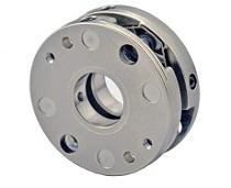 |
Configuration and materials
 |
|
 ・Key groove shape complies with new JIS standards.
Dimensions of key groove shape |
* Due to hub material, spece, and normal torque size considerations, use a small key. |
|||||||||||||||||||||||
Dimensions
| Item No. | D |
Standard hole diameters ød1,ød2 H8 (left/right can be freely combined) | L | B | F |
H (plate hole diameter) |
M | Fastening torque (N⋅m) | ||||||||||||||||||||
|---|---|---|---|---|---|---|---|---|---|---|---|---|---|---|---|---|---|---|---|---|---|---|---|---|---|---|---|---|
| TSS25 | 25 | 3 | 4 | 5 | 6 | 8 | 8.5 | 3.5 | 1.8 | 13 | 2 | 0.2 | ||||||||||||||||
|
TSS32 |
32 | 5 | 6 | 8 | 10 | 12 | 14 | 11 | 4.8 | 2.4 | 16.6 | 2.5 | 0.4 | |||||||||||||||
| TSS40 | 40 | 10 | 12 | 14 | 16 | 18 | 13.5 | 6 | 3 | 22 | 3 | 0.8 | ||||||||||||||||
Specifications
|
Item No. |
Allowable torque (N・m) |
Torsional rigidity (N⋅m/rad) |
Allowable parallel misalignment (mm) |
Radial rigidity (N/mm) |
Allowable angular (°) |
Bending rigidity (N・m/°) |
allowable end play (mm) |
Axial rigidity (N/mm) |
Maximum rotating speed (rpm) | Moment of inertia (kg⋅m2) | Mass |
|---|---|---|---|---|---|---|---|---|---|---|---|
| (g) | |||||||||||
| TSS25 | 1.2 | 400 | 0.05 | 500 | 2.5 | 0.007 |
±0.3 |
16 |
16,000 | 6.5x10⁻⁷ | 9 |
| TSS32 | 1.8 | 700 | 0.05 | 500 | 2.5 | 0.008 | ±0.3 | 10 | 12,000 | 2.5x10⁻⁶ | 19 |
| TSS40 | 3.0 | 1100 | 0.05 | 800 | 1.0 | 0.04 | ±0.4 | 8 | 8,000 | 7.2x10⁻⁶ | 32 |
・Heat resistance (ambient temperature) polyimide:-40℃ to 200℃. *Note:That 1/2 the allowable torque should be used at maximum temperature.
・Maximum torque is, as a general rule, twice the normal torque. Select a size equal to or lower than the normal torque and with an instantaneous maximum load torque equal to or smaller than the maximum torque.